Taxi Driver: Difference between revisions
From Citylan
Jump to navigationJump to search
m Created page with '{| align="right" border="1" cellpadding="3" cellspacing="0" |+ style="background:silver" | EMU Infos |- |dumper || f205v, Corrado Tomaselli |- |date || 11/12/2011 |- |emulator ||…' |
m →Files |
||
| Line 92: | Line 92: | ||
==Files== | ==Files== | ||
<gallery widths="150px"> | <gallery widths="150px"> | ||
Image: | Image:1000_main_PCB_component_side.jpg|main PCB component side | ||
Image: | Image:1000_main_PCB_solder_side.jpg|main PCB solder side | ||
Image: | Image:1000_ROMs_PCB_component_side.jpg|ROMs PCB component side | ||
Image: | Image:1000_ROMs_PCB_solder_side.jpg|ROMs PCB solder side | ||
File:1000.zip|ROMs | File:1000.zip|ROMs | ||
</gallery> | </gallery> | ||
Revision as of 21:35, 11 December 2011
| dumper | f205v, Corrado Tomaselli |
| date | 11/12/2011 |
| emulator | |
| dev |
| name | 1000 |
| description | Taxi Driver (Tehkan) |
| year | 1984 |
| manufacturer | Tehkan |
Technical references
CPUs
| QTY | Type | clock | position | function |
|---|---|---|---|---|
| 2x | M5L8255AP-5 | main board ic57,ic58 | Programmable Peripheral Interface | |
| 3x | M5L8255AP-5 | ROMs board ic1,ic32,ic64 | Programmable Peripheral Interface | |
| 3x | D780C-1 | MHz | main board ic28,ic39,ic61 | 8-bit Microprocessor - main |
| 2x | AY-3-8910 | MHz | main board ic37,ic38 | Programmable Sound Generator - sound |
| 1x | oscillator | 10.000 | X1 | |
| 1x | oscillator | 8.0000 | X2 |
ROMs
| QTY | Type | position | status |
|---|---|---|---|
| 9x | M5L2764-2 | main board 1-9 | dumped |
| 6x | M5L2764-2 | ROMs board 10-15 | dumped |
| 1x | TBP18S030N | main board ic2 | not dumped yet |
RAMs
| QTY | Type | position |
|---|---|---|
| 7x | M58725P | main board ic7,ic8,ic15,ic34,ic69,ic83,ic94 |
| 14x | M58725P | ROMs board ic7,ic54,ic62,ic63,ic70,ic78,ic79,ic85,ic86,ic115,ic116,ic121,ic131,ic132 |
PLDs
| QTY | Type | position | status |
|---|
Others
1x 22x2 edge connector (main board)
2x 50 pins flat cable connector from main board to ROMs board
1x trimmer (volume) (main board)
3x 8x2 switches DIP (main board)
1x red LED (main board)
Notes
Files
-
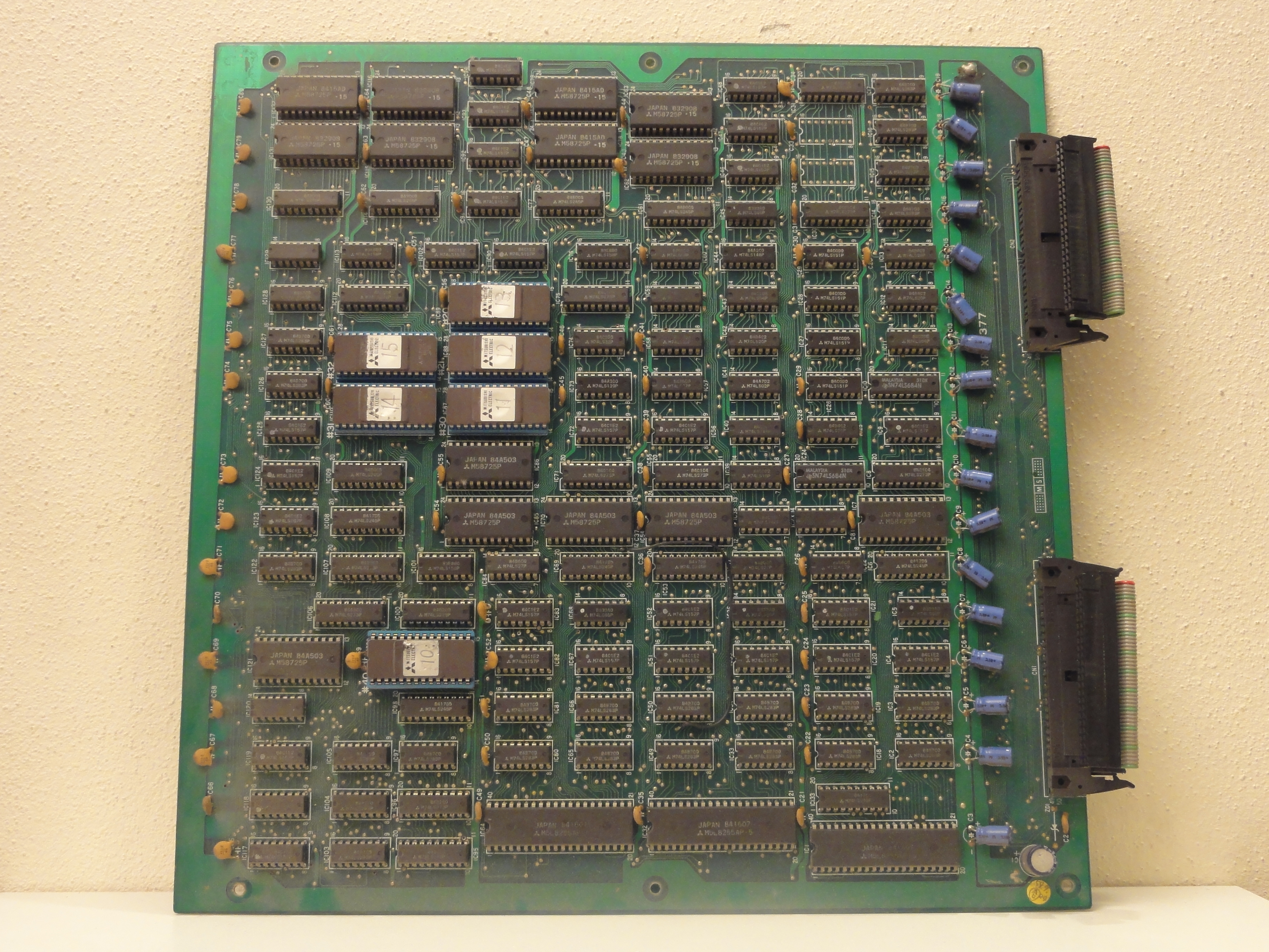
 main PCB component side
 -
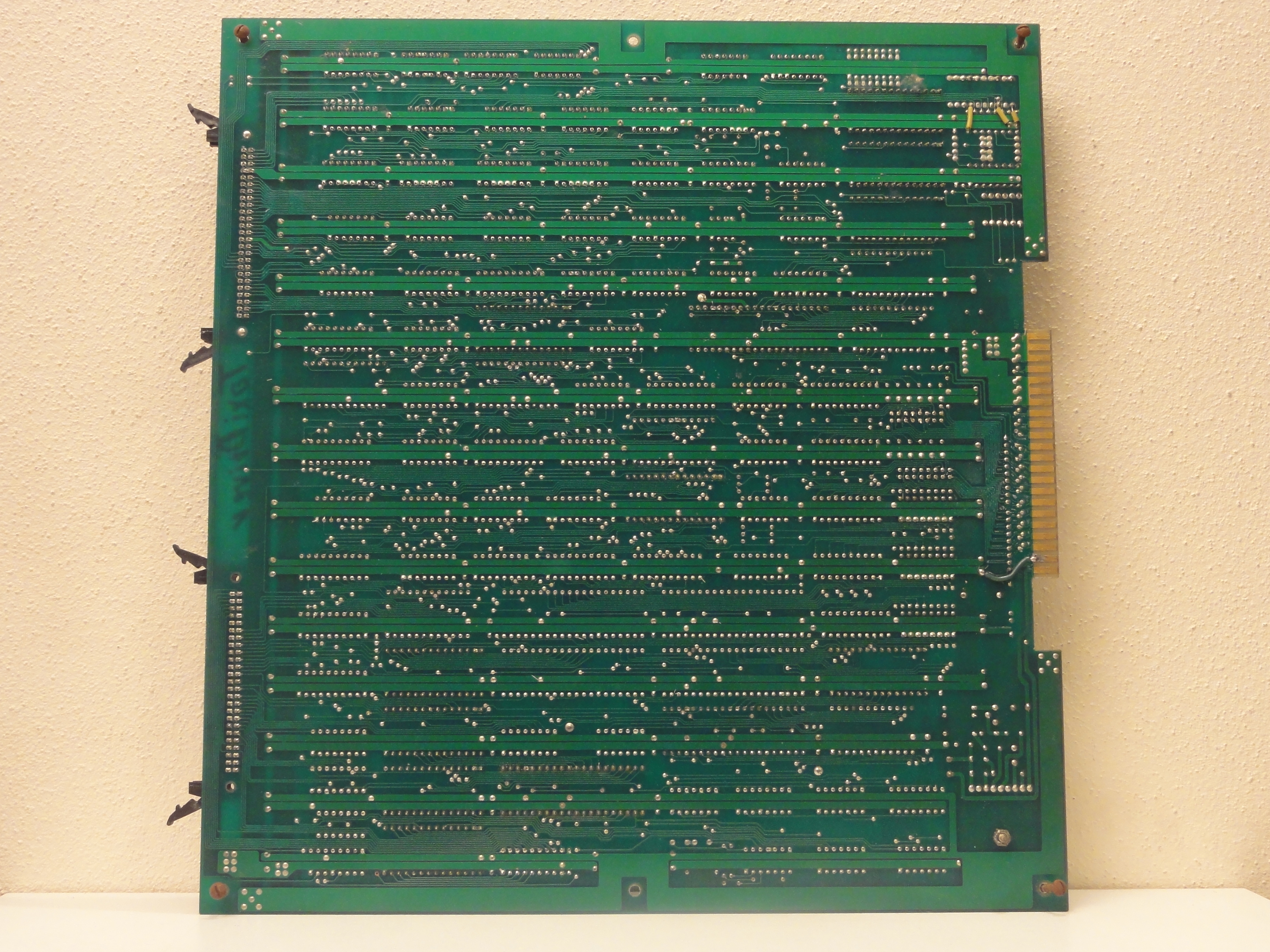 main PCB solder side
 -
 ROMs PCB component side
 -
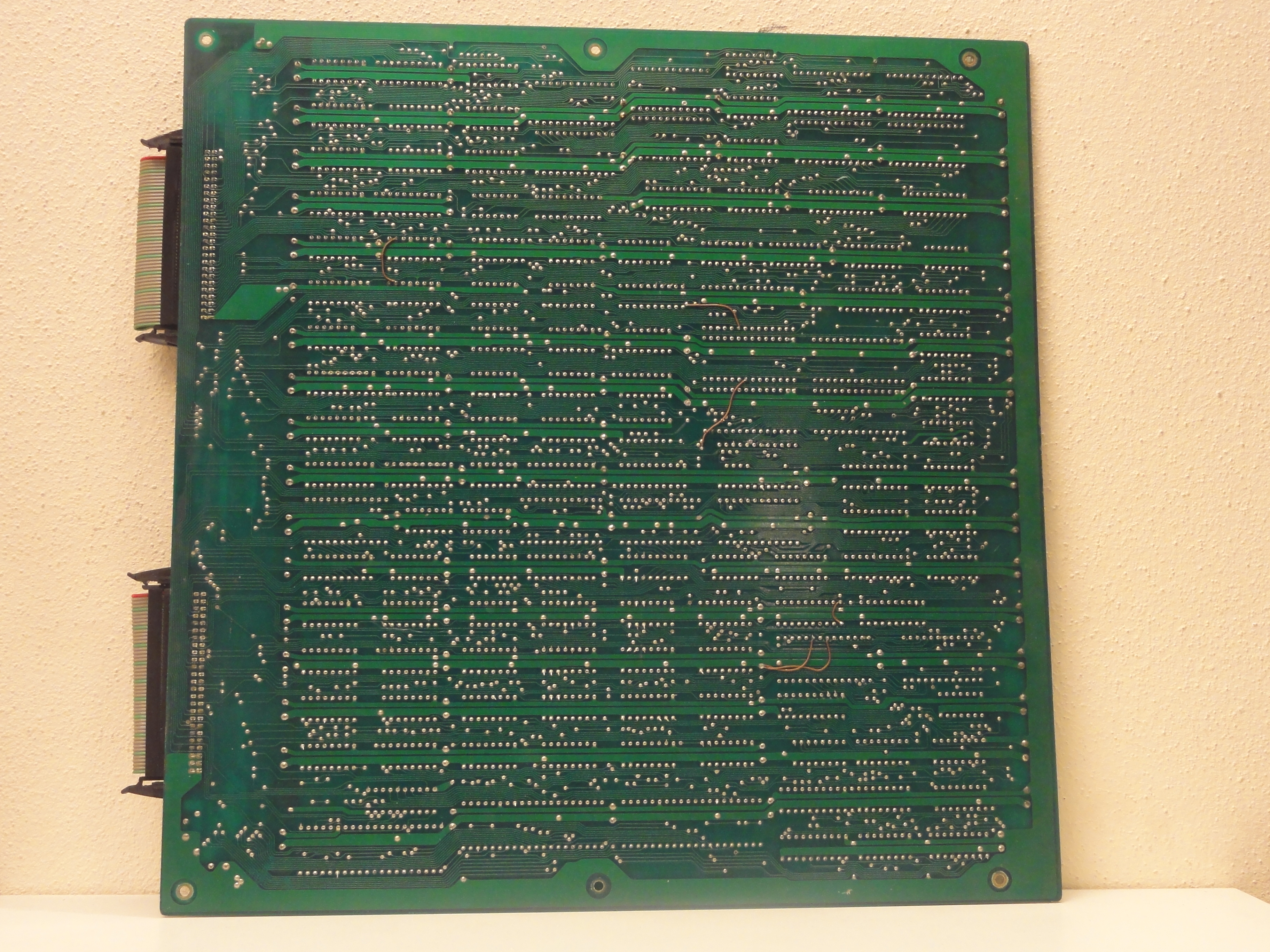 ROMs PCB solder side
 -
ROMs


1000